Posts

Showing posts from November, 2019

Manufacturing process of brick

Image
- In this article, we are discussed about "manufacturing   process of brick." first of all, we are talking about 'site   slection for manufacturing of brick.' Site slection for manufacturing of brick - - for manufacturing of brick , the following point should be   kept in your mind - (a) the ground should be levelled. (b) the available clay in this area should be pure. (c) any communicating facilities like roads should be     connected at site. (d) For labour, at least some facilities should be available,      like water, foods material or etc. site for brick manufacturing: Manufacturing process of brick - - the following steps should be used for manufacturing using   step by step - 1. Preparation of clay. 2. moulding of brick 3. drying of brick 4. burning of brick 5. Cooling of brick 1. Preparation of clay - -  the following process are used for preparation of clay-  (a) unsoiling  (b) digging  (c) cleaning  (d) weathering  (e) blendin

different types of Ingradients in cement

Image
- the following type of ingradients are mixed to manufacture   of cement. 1. Lime -    -Lime provides strength and soundness to the cement.    -Lime is also called as 'calcium oxide' and is obtained from      limestone(CaCo3)    -if lime is in excess quantity then cement makes unsound      disintegration of cement.    -if it is in low quantity then low strength are recorded. Lime powder 2. Silica(sio2)-(17-25%)-    - silica is also called as silicon dioxide and is obtained from       silicious rock. - silica also provides strength to the cement , if it is in excess    then setting time and strength of cement is more.                 silica fume 3. Alumina(Al2o3)-(3-8%)- -  Alumina is the quick setting property of cement and is     obtained from aluminium ores. -  if alumina is in excess then cement sets quickly and also     reduced it's strength. Alumina 4. Iron oxide(3-5% , <5%)- -  It provides strength, hardnes

Reason behined the use of bent-up bar

Image
Bending moment and shear force in beam- generally, we know if beam is loaded then bending moment develops, its varriation property depends on the type of beam and loading. if we take an example , in case of simplysupported moment is always zero at the support and maximum at mid span. if loading is udl then moment varriation is parabolically. moment varriation here,bending moment varies support to mid span and varriation of bending moment , shear stress developed. in case of RCC beam we assume that shear stress is carried by bonding below the nautral axis. shear stress is maximum at the support in case of simply supported , see in above figure. and bending moment is zero. if this shear stress is more than permissible then cracks are developed at 45°. this is called as diagonal tension. Reason behined bent-up bar - 1.  bent up bar provides to carry the shear stress & generally shear stress is carried by stirrups. 2.  in case of fixed beam the negative bending moment

Properties of coarse aggregate

Image
when the size of aggregate is > 4.75mm,upto 80mm then is known as coarse aggregate. 1. size of aggregate - generally the maximum size of aggregate is mostly used for construction because its specific surface area is lesser and hence less quantity of mortar is required for lubricating so increases its workability and strength. but in case of smaller size of aggregate its specific surface area of aggregate is more and then more mortar is required for lubricating and hence its workability is low and also reduces strength of concrete. larger size of aggregate is used but is also limited, it depends on following factor- a. spacing between reinforcement. b. thickness of cover. c. mixing & placing technique. generally , aggregate preffers less than spacing at least 5mm. if very larger size of aggregate is used then it creats blocking and hence reduction in strength. aggregate depends on reinforcement cover spacing 2. shape of aggregate - the shape of aggregate mostly

Design of RCC cantilever beam

Image
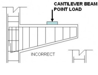
step-1   Compute depth of beam  :-                 L eff. / d  = 7              d=effective depth.                     D=d+(ⲫ / 2)+cover    ⲫ= dia of bar         generally , in case of cantilever beam moment is varied and at free                end  its value is zero , so we reduce the depth of beam at free end.         if we take an example then if 400mm depth at fixed end then at free         end provided 200mm.  cantilever beam design : step-2   loading and moment calculate & check the depth  -                 M=0.36f ck bx u (d - 0.42x u )        M= Factored moment                                                                                   b= width of beam                                                                                   d= depth of beam required                                                                                   x u = neutral axis if depth is ok then continue. step-3 compute steel  -        M= 0.87f y A st (d - 0.42x

what is plinth beam? purpose & construction.

Image
what is plinth beam  -  the beam which is provided at plinth level is called as plinth beam, if beam is provided below the plinth level then is known as tie beam. there is no difference between plinth beam and tie beam. plinth beam is shown in figure :- location of plinth beam Purpose of plinth beam  :- Plinth beam connects all the column and prevents the overlaping of structure from earthquake. plinth beam also distributes all the weight of wall which is provided above this beam. plinth beam also saves my money. Construction of plinth beam  :- plinth beam is constructed by using reinforced cement concrete. the minimum grade of concrete for plinth beam is M20 and minimum depth is 20cm(8"). when concrete is mixed by artificially then 20% extra cement must be added. concrete mixing for plinth beam Steel bars for plinth beam  - steel bar is provided 2 at top having minimum dia 12mm and two bars at bottom having minimum dia. 10mm. the stirrups are provided 6

steps to design tension member

Image
step-1    Determination of required area -                                                                               A req. = P/ σ at          where, P=total axial tension                                                                           σ at=axial permissible stress in                                                                                            tension= 0.6 f y           generally the value of  σ at varies with respect to dia of bar preffered           upto 20mm dia. permissible stress is 0.6 f y  but if bar dia increses then            permissible stress decreases. step-2   computation of gross area -             gross area varies with respect to connection of angle .               a. if two angles connected to gusset plate at one side-                       A gross = 1.35A req.                where, A gross  = gross area                 b.  if two angles connected both side of gusset plate-                                          A gross =